Shy bot – the robot which is scared of the light
Table of Contents
Creating a shy robot for a university project.
This is a translated article of mine, original can be found on Eirlab
As part of my computer science engeneering curriculum, I enrolled in an option called "Makers" during my fourth year. From this course within ENSEIRB-MATMECA's makerlab is born a shy robot, one that hates light and loves the shadows.
This article is all about explaining how it works and how you could reproduce our work, in the most "maker" spirit.
Base concept
We wanted to create a robot which would be able to detect, in real time, the brightness of its surroundings, and would then use it to go in the darkest place of the room it would be in, in order to hide (it's a shy one, remember?).
Instead of going to the darkest place it can detect, there's also another mode available, where instead of moving towards the darkest place, it tries to flee the brightest direction. Although looking similar, these two ways of thinking yield to different results.
Some hardware
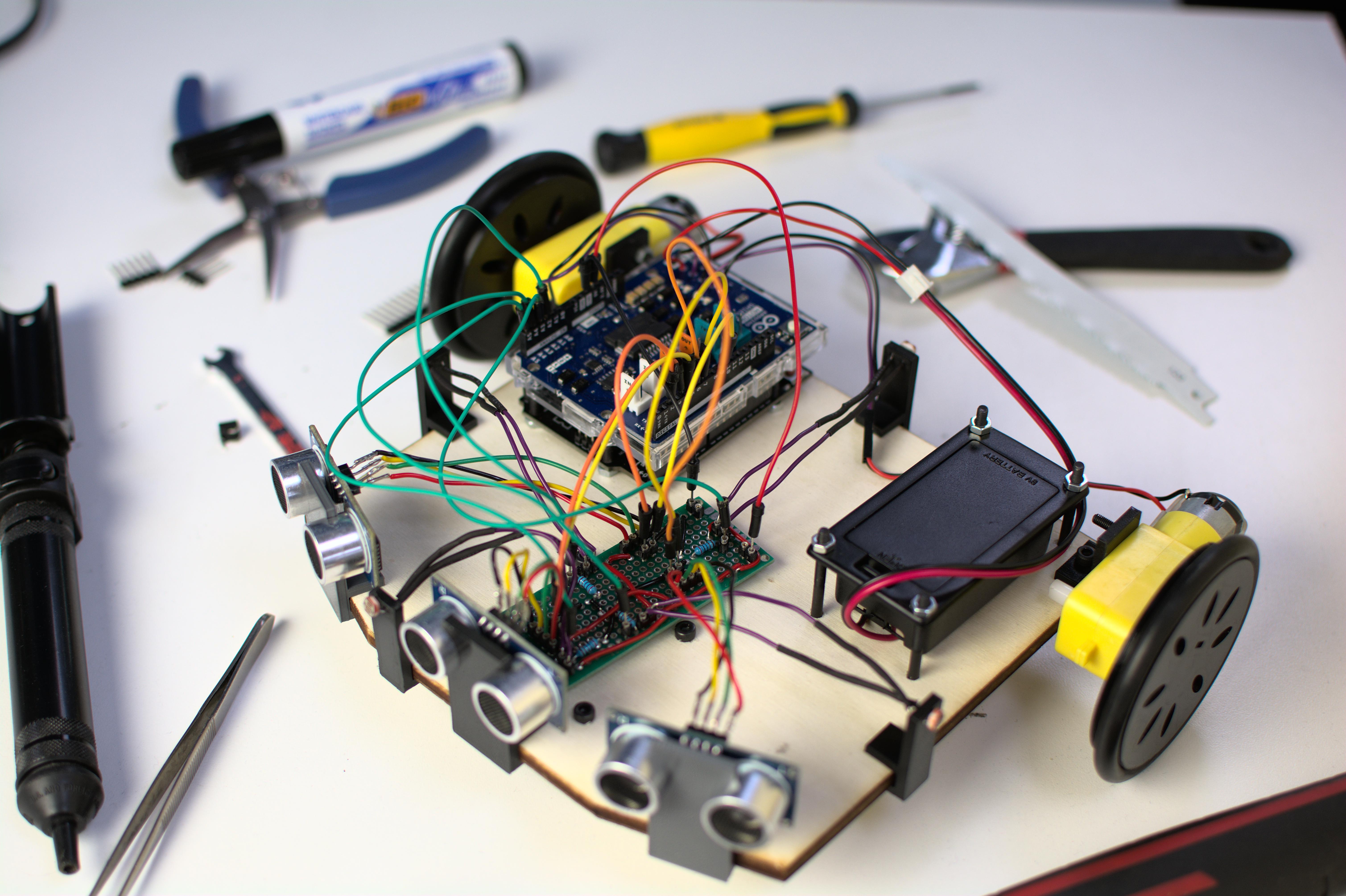
Before working on the software part of this project, we needed to have some hardware to run our code on.
It should be noted that all of the components required for this project were supplied by the fablab. We tried to only use parts that were already available, without the need to spend a single euro for this project.
Shopping list
In order to recreate this project, you would need these components:
- 1x Arduino Uno (or an equivalent clone) – it's the brains of this whole project
- 1x Arduino Motor Shield – to control the motors that will move the robot
- 2x DC motors (here FT DC 130D) – to actually move the robot
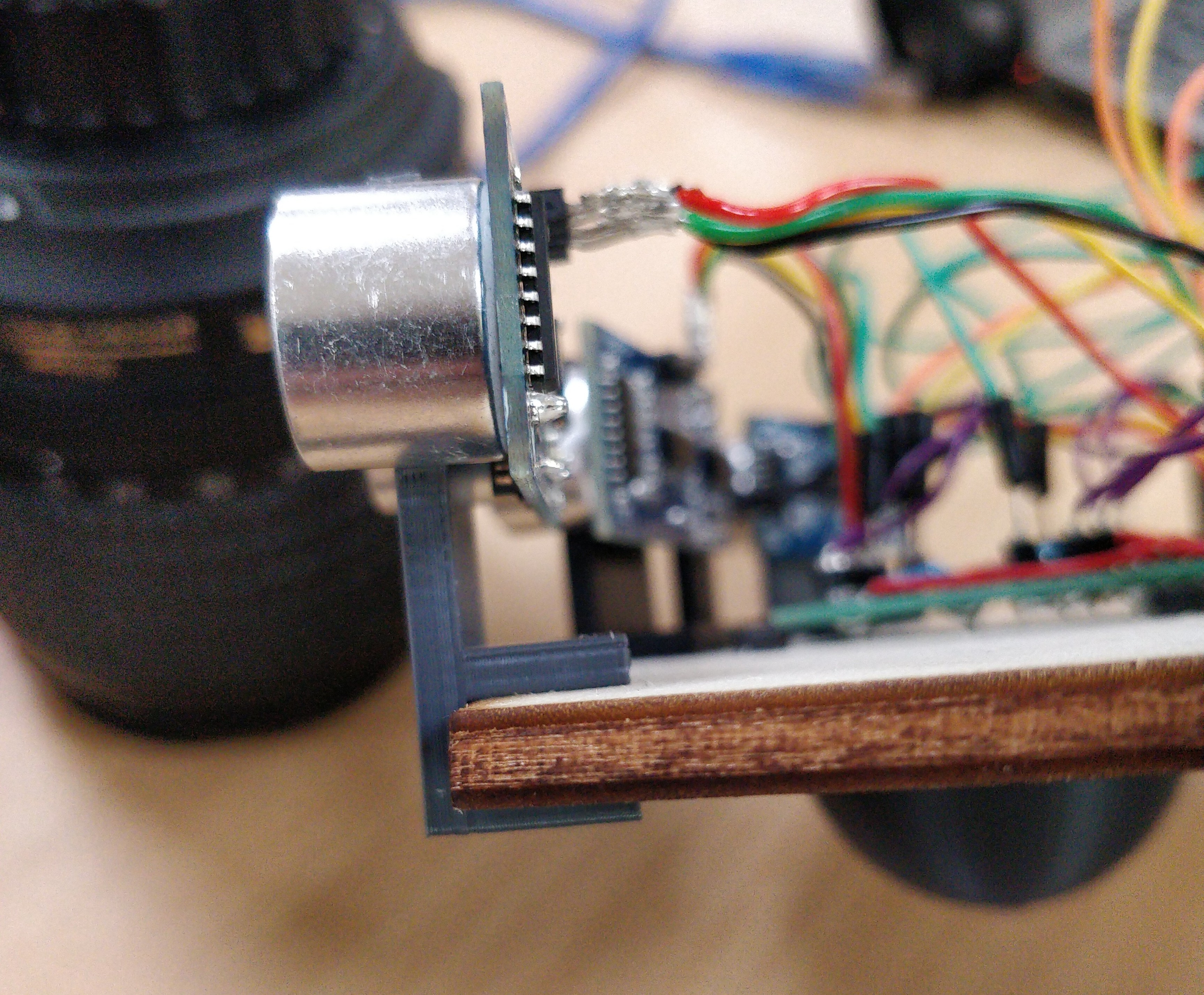
- 3x ultrasonic distance sensors HC-SR04 – to avoid hitting walls too often
- 4x photoresistors – one per side, to be able to detect brightness around it
- 4x 2kΩ resistors – for the photocell circuit, to have a better detection amplitude
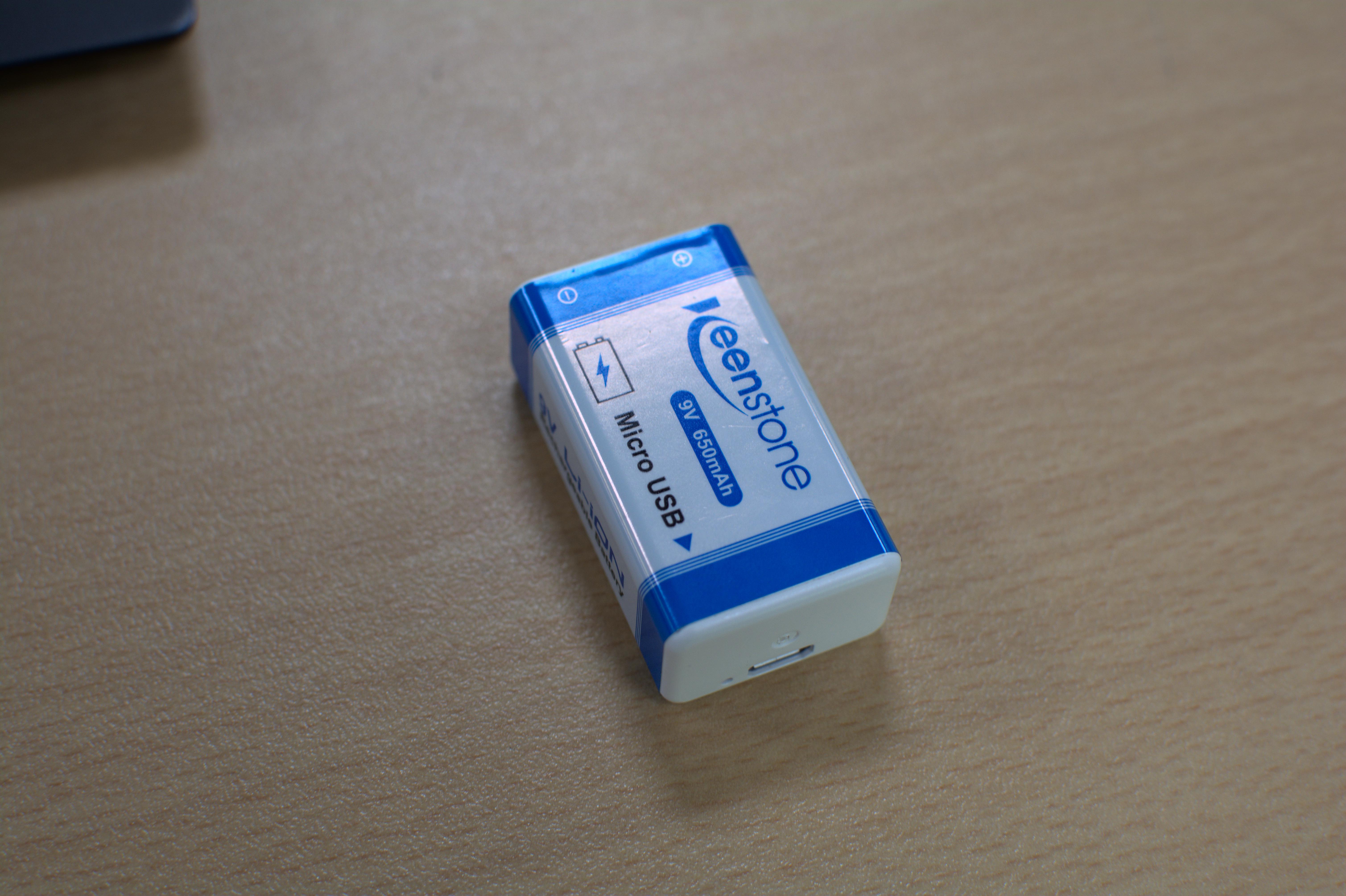
- 1x 9V battery – because it needs power to do anything
- 1x box for 9V batteries [optional] – so the battery is safely mounted
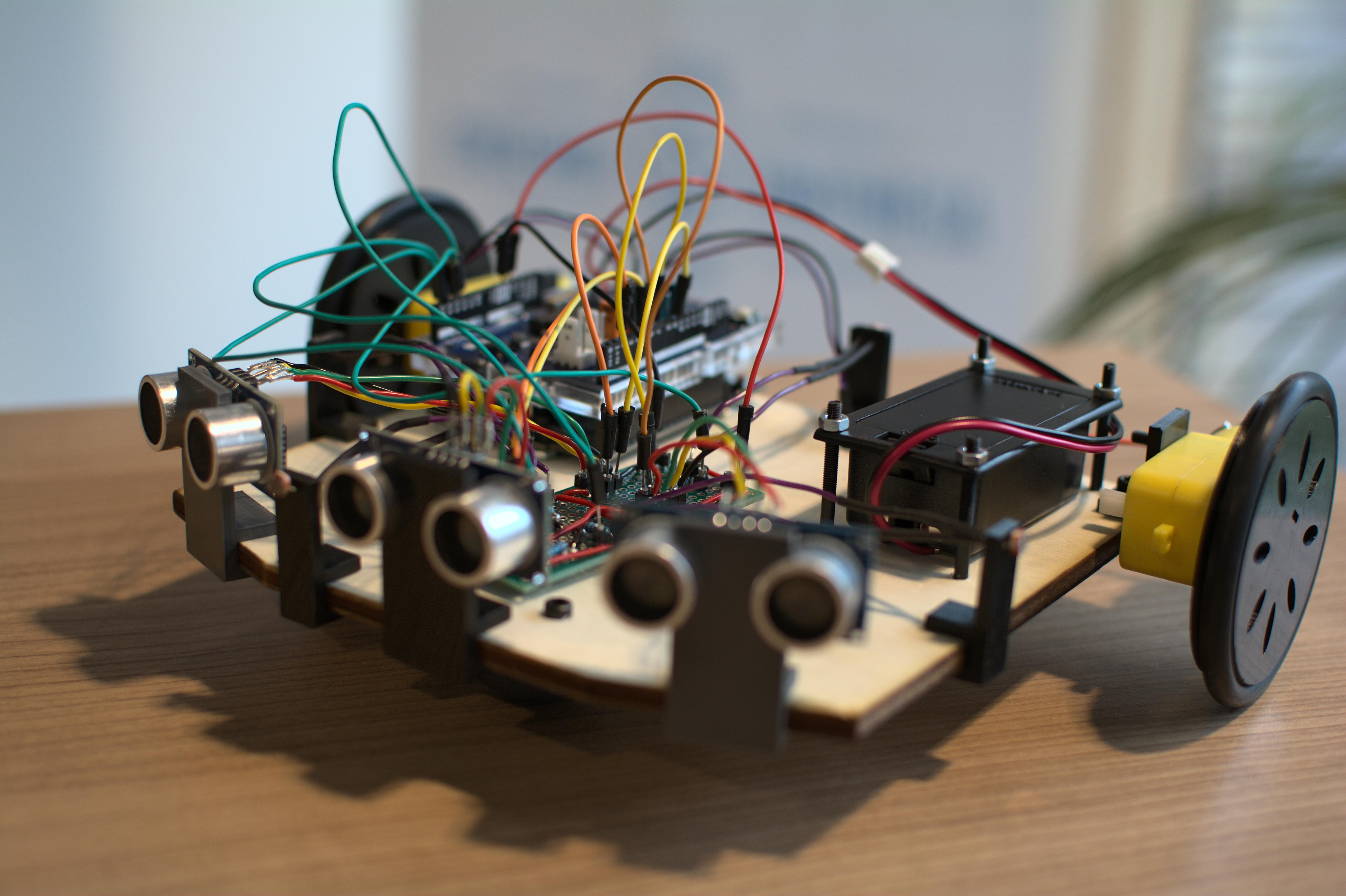
Chassis
The chassis for this robot is a piece of plywood, 5mm thick to be precise. It has been machined using a laser cutter, availabe in the fablab. This plank is about 17 by 15.5 centimeters, and has two beveled corners, which are useful so the robot can see in front of it. The bevels have a 20 degrees angle, going on 4.5cm.
The base plate is then pierced to accomodate for the different components that will need to be mounted on the said plate. The lighter components will be pressure mounted, using a u-shape that will fit around the plate's side.
Power
For powering the robot, we want to send 9 volts, from a battery or a power supply,
in the power input VIN of our Arduino board. This tension will then be regulated
on the PCB to create the different power rails that would be needed. This input is
connected internally to the barrel jack of the Arduino, which can take power ranging
from 5 to 9 volts.
In this project, we are using a 9V battery which is placed in a case that is bolted on the base plate.
Motors
The motors are bolted to the chassis in this project, because when they were mounted just using pressure, they would run away each time the robot made a rough acceleration.
These motors are directly powered and controlled using the Arduino Motor Shield,
which lets us select a speed ranging from 0 to 255 using a coding API.
This API also lets us engage brakes or set the direction in which the wheels
are turning.
The wheels for this project have been 3D printed and pressure-fit on the motors themselves, and an O-ring seal is then used to add some grip.
PCB
In the beginning of this project, we used a breadboard for electronics prototyping. We had a lot of disconnect issues, so as soon as the hardware part could be frozen, we migrated the breadboard electronics to a hand-made PCB using a prototyping board. This made the robot way more resilient to a sharp acceleration curve.
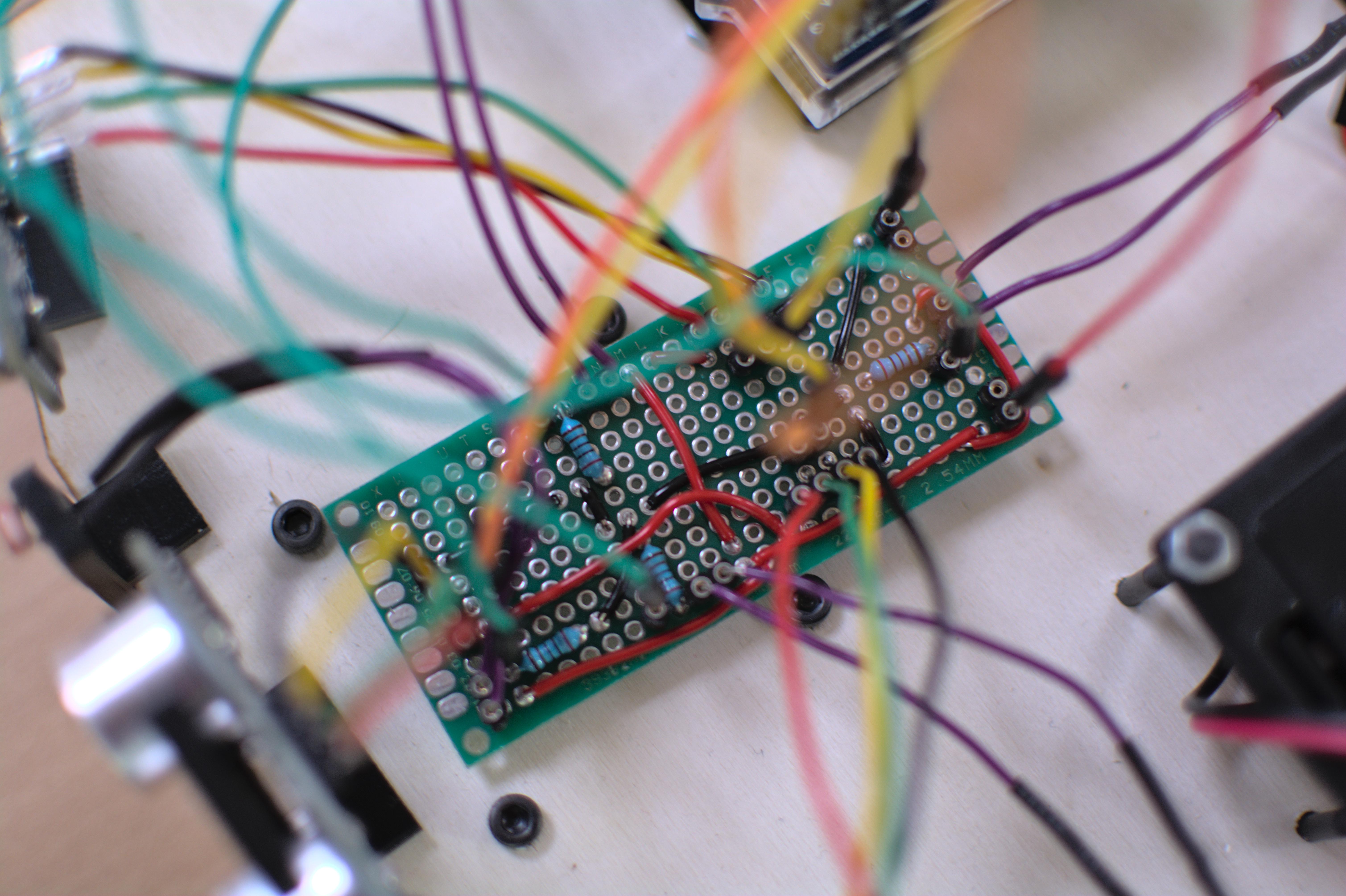
On an electronic level, the PCB is routed such as:
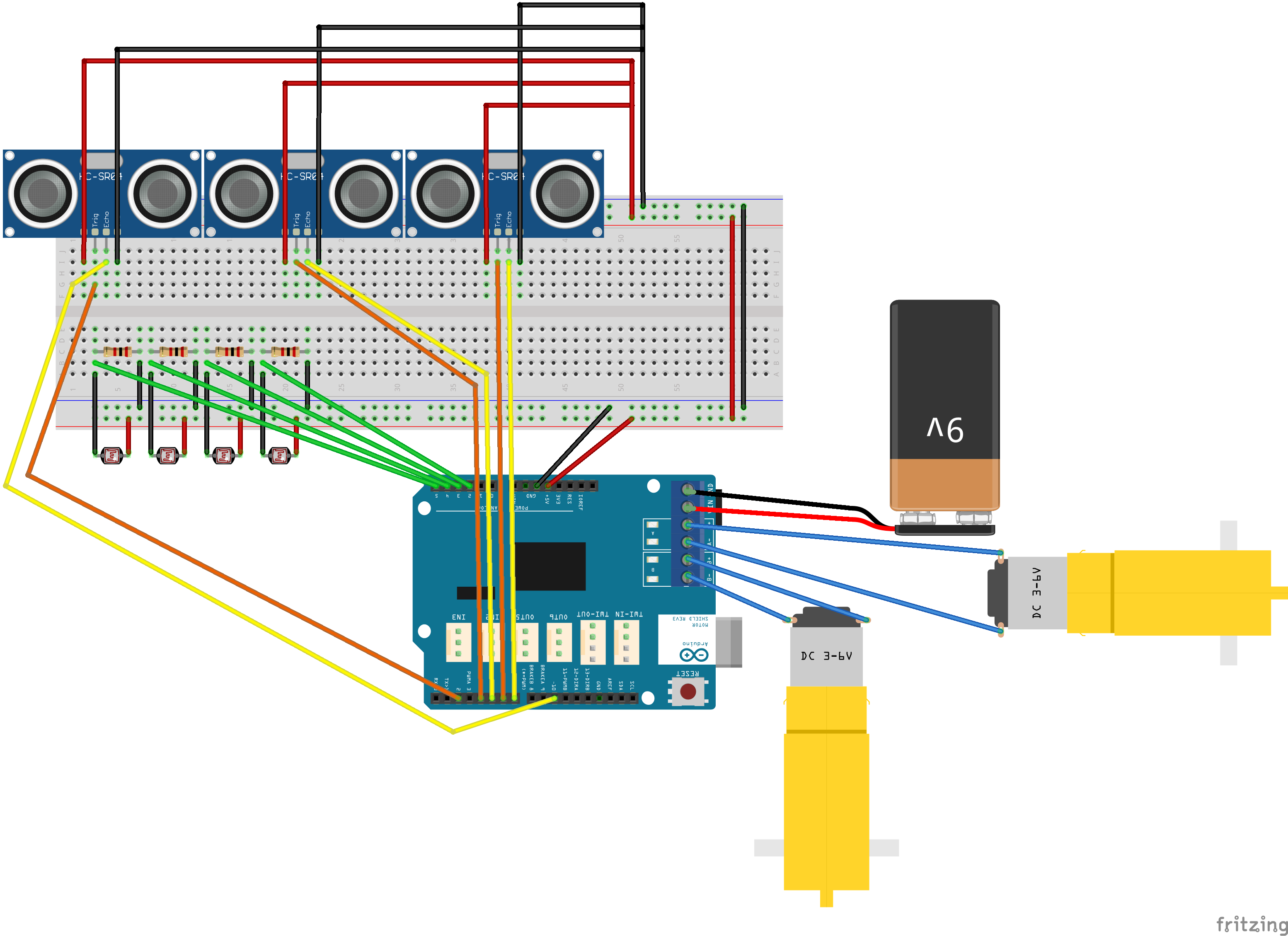
The different components are interfaced with the PCB using a kind of connector that lets us connect and disconnect things as we iterated on the sensors without having to use a soldering iron.
And finally some software
From a software point-of-view, the project is quite simple.
On a high-level, the algorithm could be summed up as follows: check all four photocells,
and move, using rotation and translation, towards the one that has the darkest value, if
followDark is set to true. If this value is set to false, then the robot will move
itself in the opposite direction to this brighest value.
A distance mesurement is made using the three ultrasonic distance sensor, so the robot is able to stop before hitting a wall (hopefully). These sensors act as "kill switches" that forbid the robot from ever moving while these sensors are detecting an obstacle.
The code is as follow:
#define echo1Pin 5
#define trig1Pin 4
#define echo2Pin 7
#define trig2Pin 6
#define echo3Pin 10
#define trig3Pin 2
#define rotMot1Pin 12
#define brakeMot1Pin 9
#define vitMot1Pin 3
#define rotMot2Pin 13
#define brakeMot2Pin 8
#define vitMot2Pin 11
#define photoRes1Pin A2
#define photoRes2Pin A3
#define photoRes3Pin A4
#define photoRes4Pin A5

#define followDark false

long duration;
int distance;

void setup() {
  Serial.begin(9600);
  pinMode(rotMot1Pin, OUTPUT);
  pinMode(brakeMot1Pin, OUTPUT);
  pinMode(vitMot1Pin, OUTPUT);

  pinMode(rotMot2Pin, OUTPUT);
  pinMode(brakeMot2Pin, OUTPUT);
  pinMode(vitMot2Pin, OUTPUT);

  pinMode(photoRes1Pin, INPUT);
  pinMode(photoRes2Pin, INPUT);
  pinMode(photoRes3Pin, INPUT);
  pinMode(photoRes4Pin, INPUT);

  pinMode(trig1Pin, OUTPUT);
  pinMode(echo1Pin, INPUT);
  pinMode(trig2Pin, OUTPUT);
  pinMode(echo2Pin, INPUT);
  pinMode(trig3Pin, OUTPUT);
  pinMode(echo3Pin, INPUT);

  delay(3000);
}

void loop(){
  byte echoPins[3] = {echo1Pin,echo2Pin,echo3Pin};
  byte trigPins[3] = {trig1Pin,trig2Pin,trig3Pin};
  long int durations[3] = {};
  long int distances[3] = {};

  for(int i = 0; i < 3; i++){
    digitalWrite(trigPins[i], LOW);
    delayMicroseconds(2);

    digitalWrite(trigPins[i], HIGH);
    delayMicroseconds(10);
    digitalWrite(trigPins[i], LOW);
    durations[i] = pulseIn(echoPins[i], HIGH);
    distances[i] = durations[i] * 0.034 / 2;
  }

  int photoRes[4] = {};
  Serial.print("Capteur infra : 1[");
  photoRes[0] = analogRead(photoRes1Pin);
  Serial.print(photoRes[0]);
  Serial.print("] 2[");
  photoRes[1] = analogRead(photoRes2Pin);
  Serial.print(photoRes[1]);
  Serial.print("] 3[");
  photoRes[2] = analogRead(photoRes3Pin);
  Serial.print(photoRes[2]);
  Serial.print("] 4[");
  photoRes[3] = analogRead(photoRes4Pin);
  Serial.print(photoRes[3]);

  for(int i = 0; i < 3; i++){
    Serial.print("] - distance(cm) : ");
    Serial.print(distances[i]);
   }

  Serial.println();

  bool b = false;
  for(int i = 0; i < 3; i++){
    if (distances[i] < 30) {
      b= true;
    }
  }

  int photoResRef = photoRes[0];
  bool photoStop = true;
  int photoResMinPos = 0;

  if (followDark){
    int photoResMin = 1024;
    for (int i = 0; i < 4; i++){
      if (photoResMin > photoRes[i]){
        photoResMin = photoRes[i];
        photoResMinPos = i;
      }
      if (abs(photoResRef - photoRes[i]) > 20){
        photoStop = false;
      }
    }
  } else{
    int photoResMax = 0;
    for (int i = 0; i < 4; i++){
      if (photoResMax < photoRes[i]){
        photoResMax = photoRes[i];
        photoResMinPos = (i + 2)%4;
      }
      if (abs(photoResRef - photoRes[i]) > 20){
        photoStop = false;
      }
    }
  }
  Serial.println(photoResMinPos);

  if (b || photoStop){
    digitalWrite(brakeMot1Pin, HIGH);
    digitalWrite(brakeMot2Pin, HIGH);
  } else {
    digitalWrite(brakeMot1Pin, LOW);
    digitalWrite(brakeMot2Pin, LOW);
  }

  if (photoResMinPos == 0){
    digitalWrite(rotMot1Pin, LOW);
    digitalWrite(rotMot2Pin, LOW);
  }
   if (photoResMinPos == 1){
    digitalWrite(rotMot1Pin, LOW);
    digitalWrite(rotMot2Pin, LOW);
  }
   if (photoResMinPos == 2){
    digitalWrite(rotMot1Pin, HIGH);
    digitalWrite(rotMot2Pin, HIGH);
  }
   if (photoResMinPos == 3){
    digitalWrite(rotMot1Pin, HIGH);
    digitalWrite(rotMot2Pin, LOW);
  }
  analogWrite(vitMot1Pin, 150);
  analogWrite(vitMot2Pin, 150);
}
Thanks
We wanted to say thank you to the ENSEIRB-MATMECA, to our fablab, EIRLAB, for trusting us, helping us and providing the hardware we used throughout this project.
Thank you also to the fab-managers who helped us and answered all of our questions, more or less asked under fatigue.
In memory of Kaitlin Rooke.